Power supply for bare ESP 8266 units
For battery powered ESP 8266 projects we would like to have a full control over electrical components that we use on board. This is because everything that draws power will also drain our battery, and this is something we want to avoid. The Wemos D1 Mini module seems to have the lowest memory consumption of them all, but we can still be better. In my battery powered projects I use ESP-12F modules and custom power circuit, that I would like to describe in this post. By the way, this approach will work with all other “bare” ESP modules like ESP-01, ESP-07, ESP-12S to mention just a few.
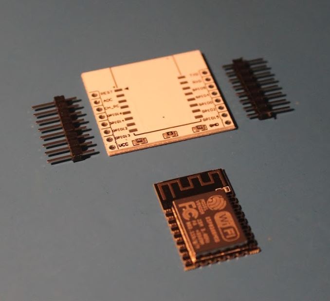
The ESP-12F module is a member of so-called castellated module family, that is it is not ready to be used with 2.54 raster boards or breadboards. Castellated modules are designed for mounting on top of other boards using SMD technique. Such modules we can find mounted on top of Wemos D1 Mini, NodeMCU v1, v2 or v3. Luckily it is possible to obtain dedicated breakout boards and solder ESP module on top of it. It is even possible to use regular soldering iron to do this, we just need a little practice in soldering.
How to start a bare ESP 8266?
We all know that ESP 9266 chip requires 3.3V DC to operate. So it’s enough to connect the “+” with VCC pin and the “-” with GND pin, and our chip will boot. We’ll, not really. We use bare ESP chip which means that we have to take care of the proper pin configuration during startup, otherwise the chip does not boot, even though it is properly powered. Let’s see the schematic.
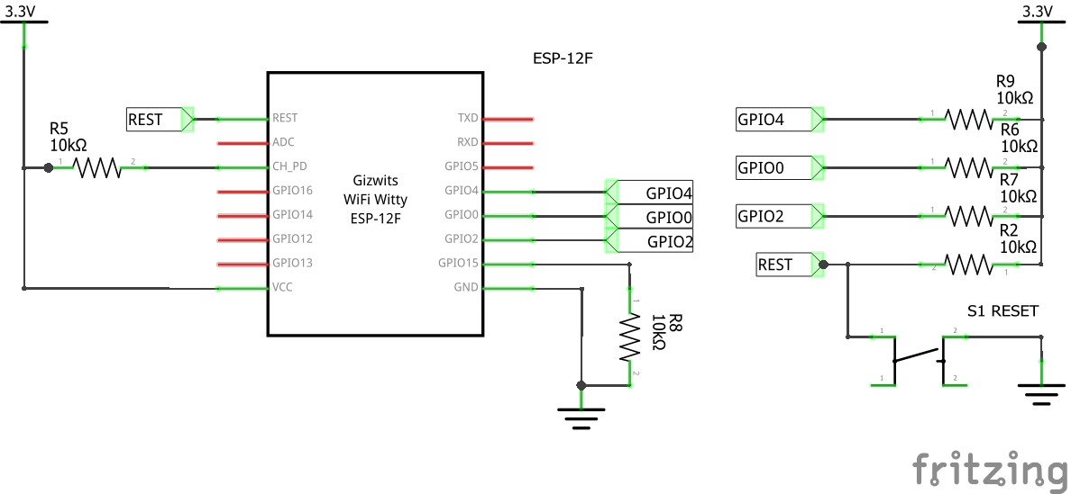
For ESP-12F to start, the CH_PD, GPIO4, GPIO0, GPIO2 pins must be pulled up and the GPIO15 must be pulled down. As pull up/down we use 10kOhm resistors that are connected with 3.3V and GND, respectively. Only with this configuration our chip properly boots up once powered.
Some breakout boards have some of these pull up/down resistors already mounted. In case of the board I use I have already CH_PD pulled up, and GPIO15 pulled down, so I can remove two resistors from by project.
Reset button
Our bare chip does not have a reset button. Because it is convenient to have one, it is good to mount it in our project. For reset button to work we need additional pull up resistor (again 10kOhm) connected to the REST pin, and a button (S1) which shorts REST line with GND. If we don’t need that button, it would be a good idea to keep REST pin pulled up all the time.
Voltage considerations
The ESP 8266 runs with 3.3V, this is also the maximal voltage accepted by any IO pins (except ADC, which accepts 1V max, funny). According to the spec, allowed voltage for VDC pin should be somewhere between 3 and 3.6V. Slightly lower voltage will work as well, but below 2.7V the operation starts to be unstable. Slightly higher voltage will not kill it immediately according to my recent experience as long as you notice your mistake and disconnect within few seconds. Voltages around 2.5V will make ESP 8266 rebooting in a loop. During reboot there is a current peak on the unit which may result in self frying, so we definitely should avoid going way below 3.0V of input voltage.
Current peaks
One nasty characteristics of ESP 8266 are current peaks during boot up. Normal current while operating are around 70-80mA but during startup we can have peaks of around 150-200mA. These are very short (few miliseconds) but significant. It took me few hours to find out why my prototype built with cheap breadboard does not work. Even if my battery was fully charged and gave good 3V when disconnected, the ESP-12F didn’t boot when connected and started to blink led regularitly (rebooting). If I measure voltage I saw a huge drop to 2.5-2.7V. And current was way above 200mA all the time - surprisingly high.
I started to google and found this excellent article. I didn’t build this complex circuit but I learned one thing: never connect ESP module to the power supply prototyped on breadboard: the connections of the breadboard have few ohms of resistance and this is enough to produce huge voltage drops due to initial current draw of ESP 8266.
The regulator
After this a bit lengthy introduction I would like to present my power supply solution for “bare” ESP 8266 modules.
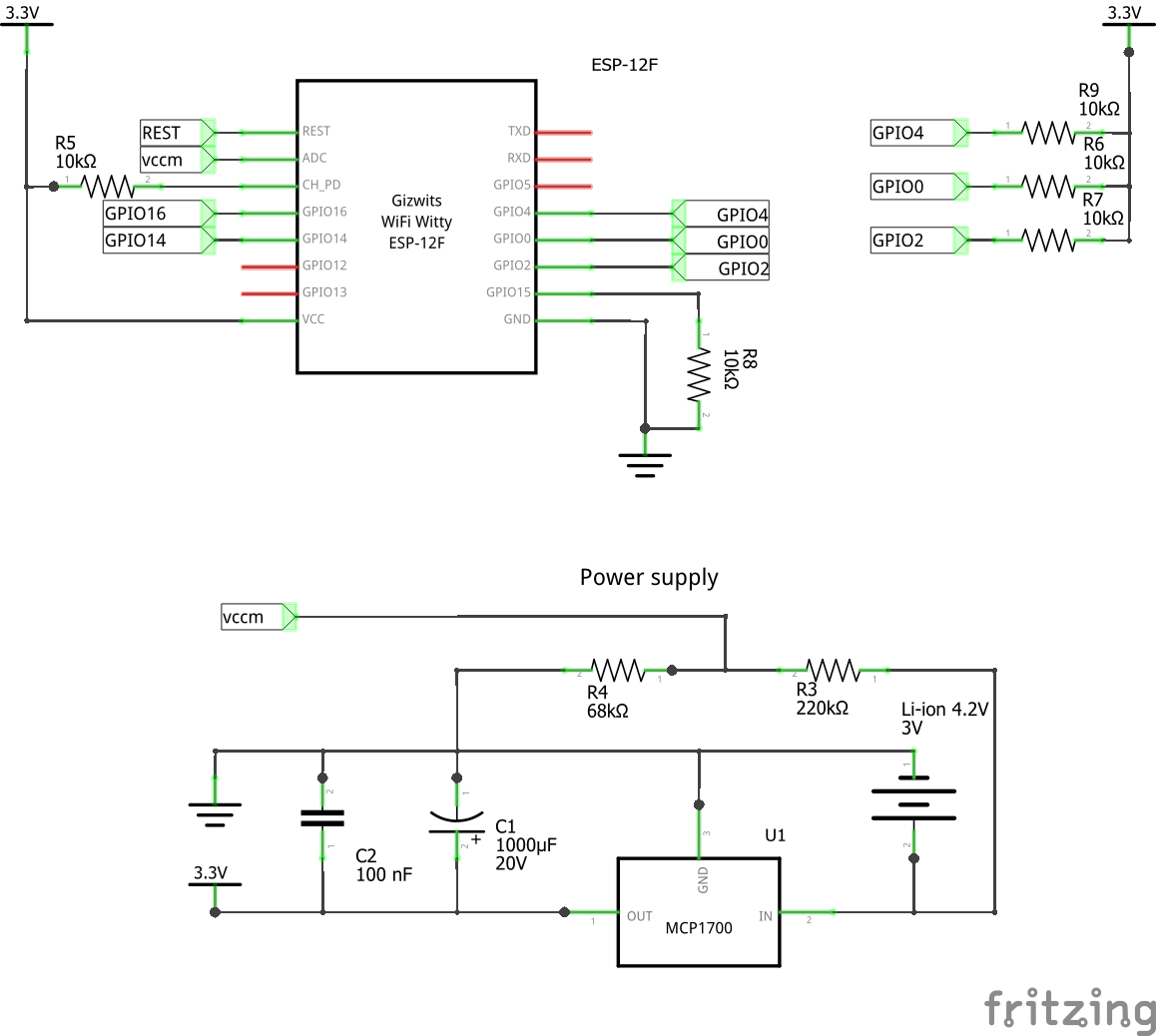
I built this unit around MCP1700-3302E/TO LDO voltage regulator which has a few nice characteristics:
- output voltage limited to 3.3V,
- input voltage range from 2.4 to 6V,
- very low dropout voltage of 178mV,
- max current 250mA (I didn’t have problems with that due to filtering capacitors).
The MCP1700 is great for battery powered projects. Don’t even think on replacing it with ordinary linear regulator.
The filter
As already mentioned, the ESP tends to generate very short current peaks that we would like to eliminate. I did it with two capacitors: electrolytic C1 (1000uF) and ceramic C2 (100nF). This setup seems to be sufficient as I have already built four devices with either ESP-07 or ESP-12F and had no stability problems related to voltage or current fluctuations.
The power source
I currently experiment with two formats of power cells:
- single Li-ion cell in 18650 standard,
- 3xAA Ni-MH cells.
The maximal voltage for 18650 does not exceed 4.2V, fully charged AA cells gives around 3.9V in series. Both solutions can be used with MCP1700 regulator. Remember that 3xAA takes more place than single 18650.
Beware of fake 18650 cells - as for 2020 the maximal capacity for this type of accumulators does not exceed 3500mAh. If somebody offers you much more for a bargain price, you should be at least suspicious.
Voltage measurement
The maintenance effort of battery powered units can be greatly lowered via VCC measurement that is sent together with other readouts. Assuming the maximal voltage would be 4.2V we can build simple voltage divider and connect it to ADC port of the ESP unit. This is done by R3 and R4 resistors. I use high resistance values to limit the current flow thru divider thus reduce power consumption of it.
Summary
I use this design in four devices using both 18650 and AA batteries. Works great so far and it is relatively cheap to build. I recommend it as long as you don’t use breadboards (which you should never use for ESP 8266 modules). It is better to do prototyping with prototype boards such as Wemos D1 Mini od NodeMCU.